
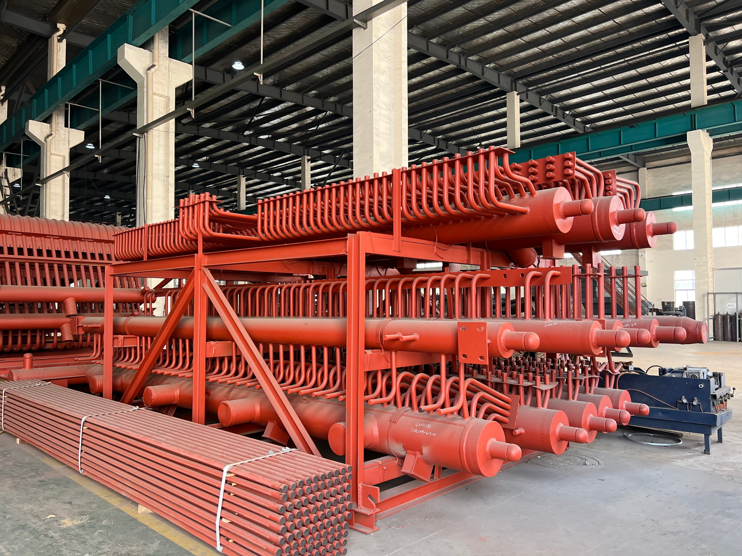
Boiler Headers
Custom-fabricated pressure-part headers and manifolds for power boilers, waste heat boilers, and package boilers. Every header is engineered to the specific boiler drawing — shell OD, wall thickness, material grade, nozzle list, and applicable code all confirmed before fabrication begins.
Fundamentals
What Is a Boiler Header?
A boiler header is a pressure vessel — typically a thick-walled pipe or forged cylinder — that collects flow from multiple parallel tubes into a single outlet, or distributes flow from a single inlet into multiple parallel tubes. Every economizer, superheater, reheater, and water wall panel in a power boiler connects to at least two headers.
How Headers Work in a Boiler Circuit
Where Headers Are Used
- Economizer inlet & outlet headers
- Superheater & reheater headers
- Water wall lower & upper headers
- Convection tube bundle headers
- Attemperator (spray water) headers
- HRSG module inlet/outlet headers
Product Range
Header Types
Headers are classified by their position in the boiler circuit — which determines the design pressure, design temperature, material grade, and the PWHT requirement. All three types are within ORL Power's certified scope under ASME Section I and GB/T 16507.
Economizer Headers
Inlet and outlet headers for economizer coil banks. These carry feedwater at boiler design pressure at the lowest temperature in the circuit — typically 150–350°C. Carbon steel is standard. Tube stub counts of 40–200+ per header make nozzle layout precision critical for even flow distribution.
- Highest tube stub density of any header type
- End caps, drain, vent, and inspection nozzles
- Individual headers or matched inlet/outlet pair
Superheater & Reheater Headers
Headers for the hottest zones of the boiler — superheated steam at high pressure up to 620°C. Chrome-moly (P11, P22) is standard; P91 is used for ultra-supercritical and reheater service. Material certification and PWHT records are mandatory on every weld seam.
- PMI on every P91 nozzle and shell section
- PWHT time-temperature chart issued per weld seam
- Post-PWHT hardness test per ASME requirement
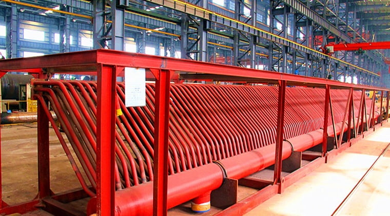
Water Wall Headers
Lower and upper headers for membrane water wall panels — large-bore, heavy-wall, with one tube stub per water wall tube. On a large furnace panel this means 100–400 stubs per header. Stub spacing and projection length must match the panel fabrication drawing exactly.
- Stub layout dimensioned from panel drawing
- Pre-assembled with wall panel (optional)
- Downcomers, risers, and tie-in nozzles included
Headers Are Always Supplied Complete
A header is not just a pipe with holes — it is an assembly that includes end caps or dished ends, all nozzle forgings (tube stubs, main connections, drain, vent, inspection), saddle supports, nameplate, and hydrostatic test certification. ORL Power supplies every header as a complete, tested, code-stamped assembly ready for installation.
If your project requires headers together with the tube coils or panels they connect to — economizer coil + headers, superheater + headers, water wall panel + headers — we can supply the complete assembly from one source, with a single set of code documentation.
Not sure which type or material grade applies to your project? Send your design pressure, design temperature, and applicable code — we'll advise.
Get Technical AdviceQuality Assurance
Materials & Standards
Header material grade is determined by design temperature and the applicable code. ORL Power confirms the grade selection against your design conditions at drawing review — not just fabricates to whatever is specified without a check.
Material Grade by Design Temperature
PWHT — When It Is Required
P91
In-house furnace: ORL Power operates a dedicated heat treatment furnace large enough for full header assemblies — not outsourced to a subcontractor. Temperature uniformity, hold time, heating and cooling rates are monitored by calibrated thermocouples. The time-temperature chart is part of the standard documentation package.
Certifications & Capability Evidence
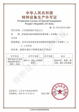
Grade A Boiler

ISO 9001

ISO 14001

ISO 45001
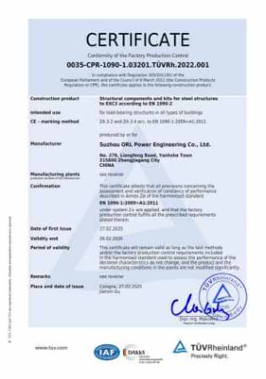
EN 1090

EN 3834
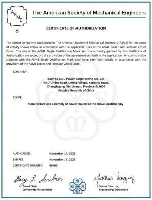
ASME S
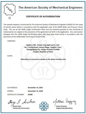
ASME U
Our Advantage
Why Choose ORL
Headers are the single point of failure for an entire tube bank — one cracked nozzle weld or an out-of-tolerance stub position can ground the whole boiler. The six points below reflect where we have invested to make header failures uncommon rather than inevitable.
Drawing Review Before Fabrication
Before we write a weld procedure or cut material, our engineering team checks your header drawing for wall thickness adequacy, nozzle reinforcement, and PWHT requirement. If we find an issue — under-sized wall, missing reinforcement pad, wrong material grade for the temperature — we raise it in writing. This review is part of the service, not a consulting add-on.
Stub Position Accuracy ±1 mm
Tube stub position errors accumulate — if a 100-stub header has each stub ±3 mm out of position, the last stub is far enough off to prevent the tube coil from connecting without forcing. We manufacture stub positions to ±1 mm on pitch and verify with a dimensional inspection report before the header leaves the shop. This is confirmed in the shipping documentation.
In-House PWHT Furnace
Heat treatment is performed in our own furnace — not sent out to a subcontractor with a different quality system. We control the time-temperature cycle directly, monitor with calibrated thermocouples, and issue the chart as part of the standard documentation. For P91, this is critical: a PWHT performed at the wrong temperature produces a soft, creep-prone microstructure that looks fine at ambient temperature but fails prematurely in service.
Full NDT — Weld Seams and Nozzles
All pressure welds on ASME and GB headers are subject to radiographic or ultrasonic examination per the applicable code. Nozzle fillet welds receive magnetic particle or dye penetrant inspection. The NDT report identifying weld locations, test method, and acceptance is part of the standard documentation — not a separate purchase.
Complete Pressure Parts Package
Headers fabricated at ORL Power can be supplied as part of a complete tube bank — economizer coils + headers, superheater coils + headers, water wall panels + headers — with a single code data report covering the whole assembly. This eliminates the interface between a header fabricator and a tube manufacturer, which is where most fitment problems originate.
Outage Schedule Discipline
Header replacement or new supply is typically on the critical path of a boiler outage or a new plant commissioning schedule. We provide a fabrication milestone schedule at order confirmation — material receipt, fit-up, welding completion, PWHT, NDT, hydro test, despatch — and update it weekly. Slippage is flagged before it becomes a site delay.
Send us your header drawing and design conditions.
We'll confirm material grade, PWHT requirement, and delivery schedule in one reply.
Applications
Industries We Serve
Every steam-generating boiler contains headers. The buyer is typically an EPC contractor building a new plant, a boiler OEM supplying a packaged unit, or a plant owner replacing worn headers during a scheduled outage.
Power Plants
Coal-fired, gas-fired, and biomass power station boilers. Superheater and reheater outlet headers in P22 or P91 for high-temperature high-pressure service. Economizer and water wall headers in carbon steel for the lower-temperature circuits.
Sugar Mills & Cogeneration
Bagasse-fired cogeneration boilers for the sugar industry. Headers for economizer and superheater circuits of 20–60 bar boilers. Replacement headers for plant life extension — matched to existing tube coil geometry to avoid panel redesign.
Waste Heat Boilers
HRSG modules for gas turbine combined cycle plants. Evaporator, economizer, and superheater headers for cement kiln, glass furnace, and steel mill waste heat recovery boilers. Clean gas conditions allow compact header design with many nozzle connections.
Biomass & Waste-to-Energy
Wood chip, agricultural residue, and municipal solid waste boilers. Operating pressures and temperatures comparable to conventional industrial boilers. Headers supplied as part of complete pressure parts packages — economizer, water wall, and superheater headers in a single order.
Tell us your boiler type and operating conditions.
We'll confirm header type, material grade, and lead time in one reply.
Manufacturing Process
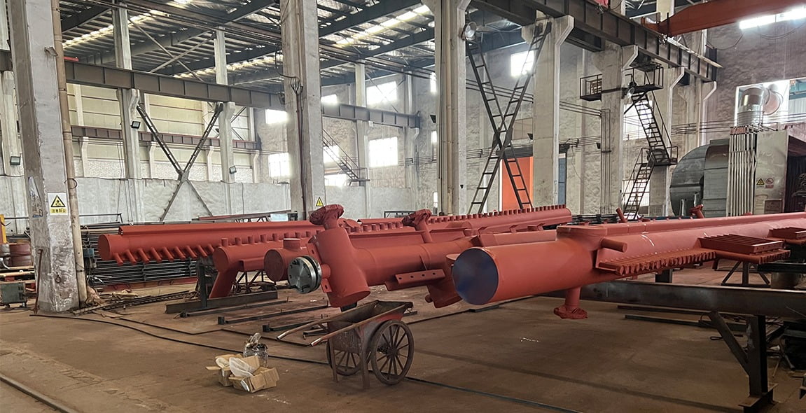
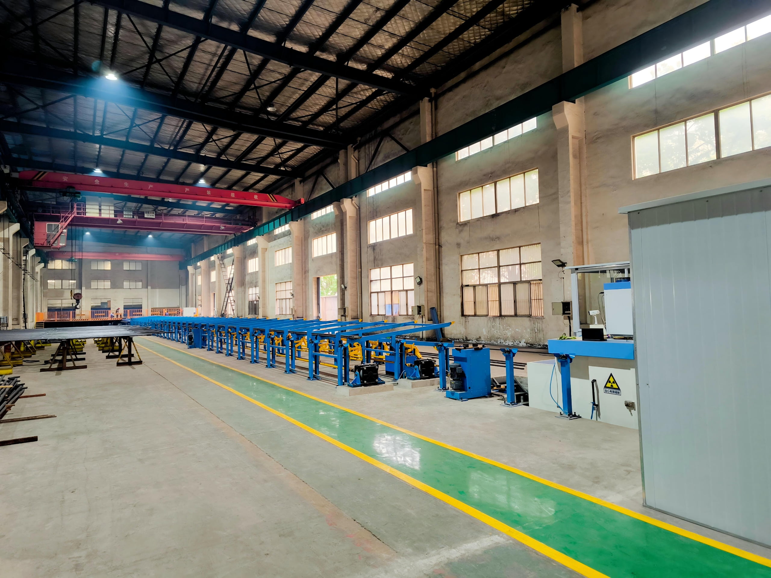
Factory & Production
Header fabrication involves more sequential steps than most boiler components — incoming inspection, machining, fit-up, welding, PWHT, NDT, and hydrostatic test must all be completed and documented before despatch. Each step is tracked against the production schedule.
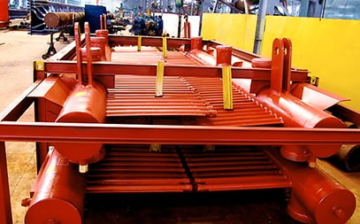
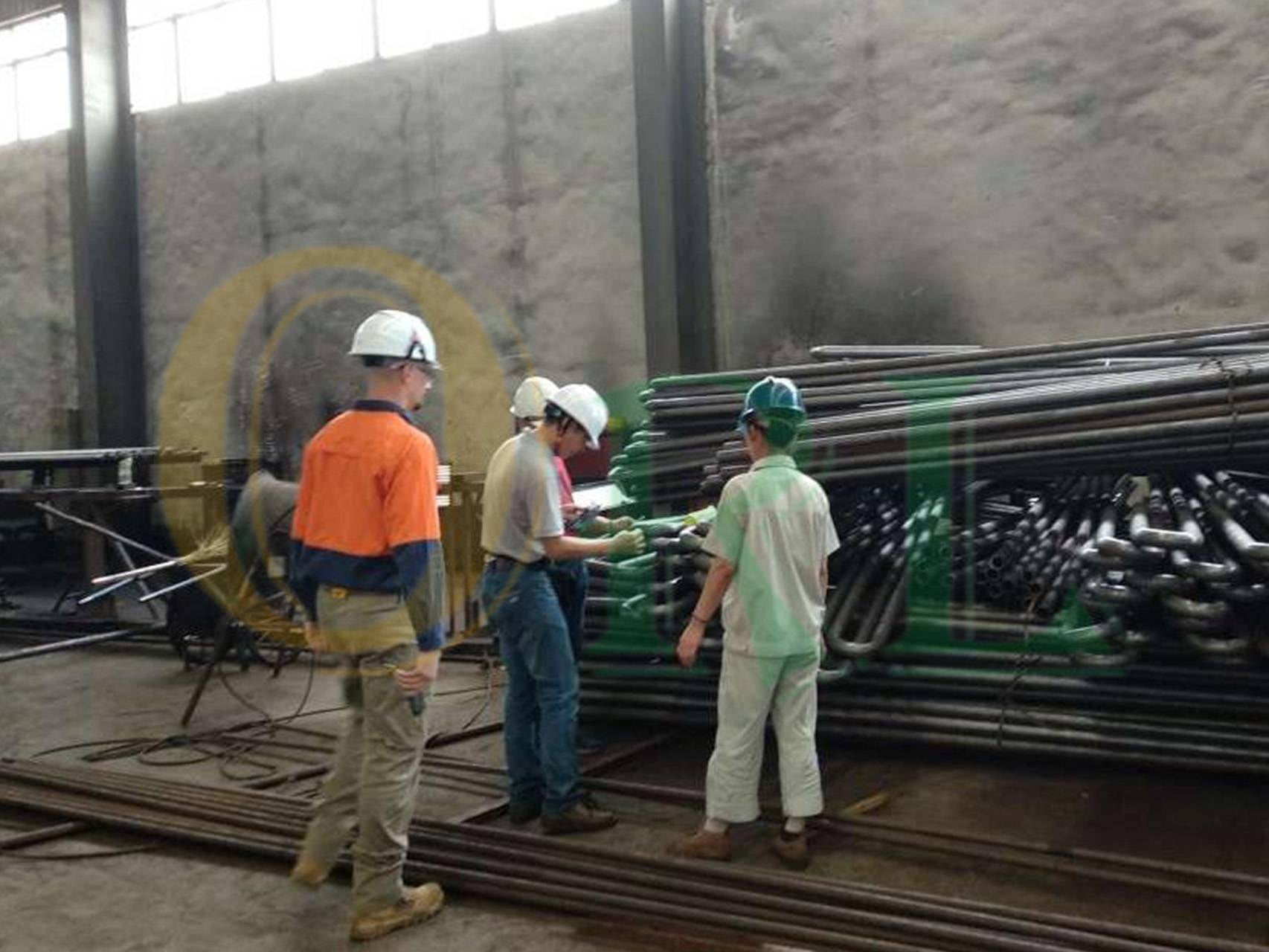
Key Production Steps
Header nozzle welding
Hydrostatic testing
Dimensional inspection
Customer Visits & Factory Evidence
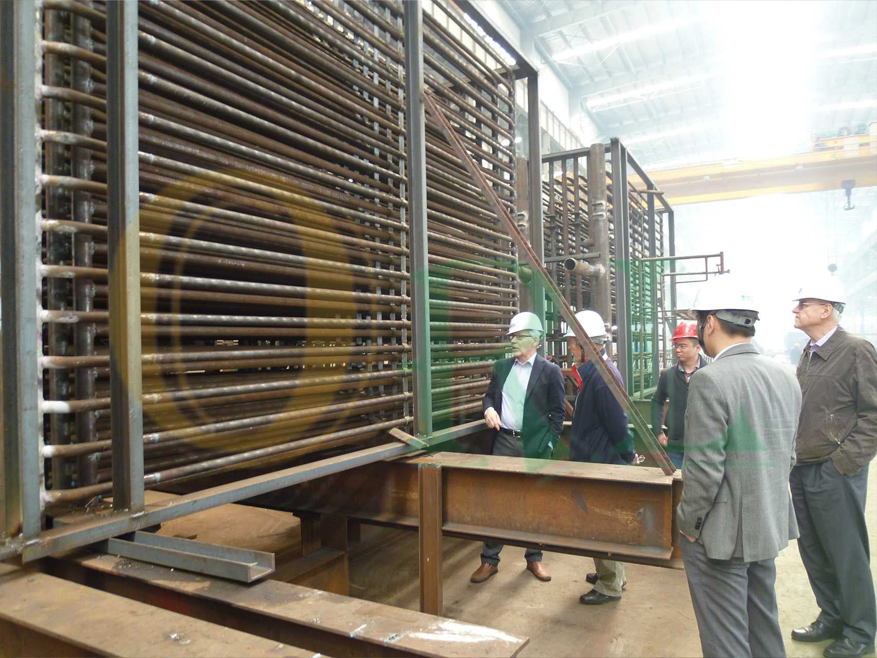
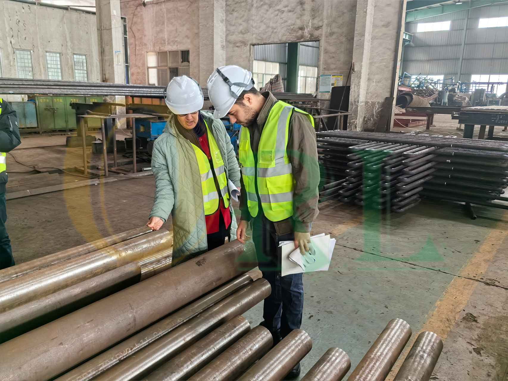
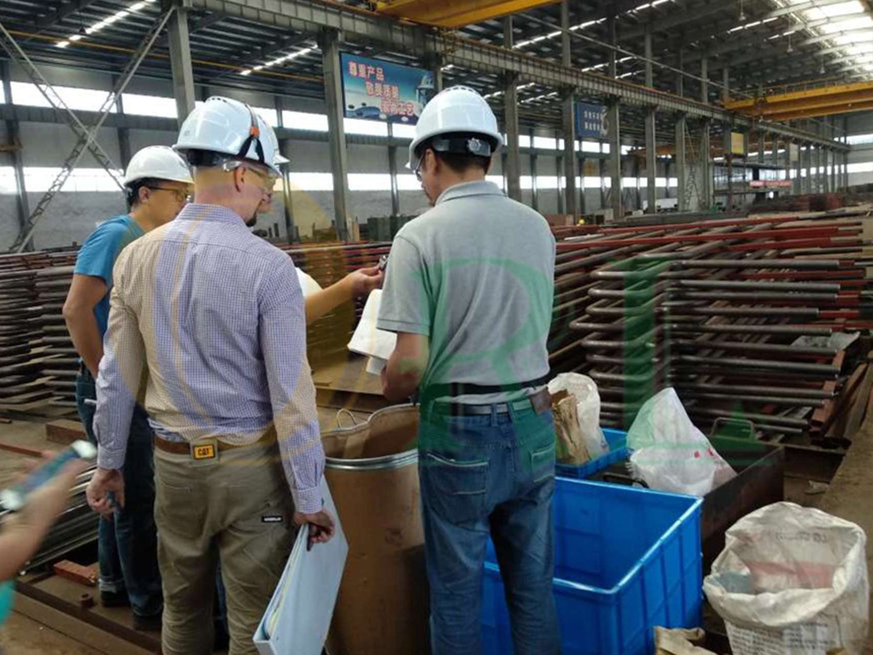
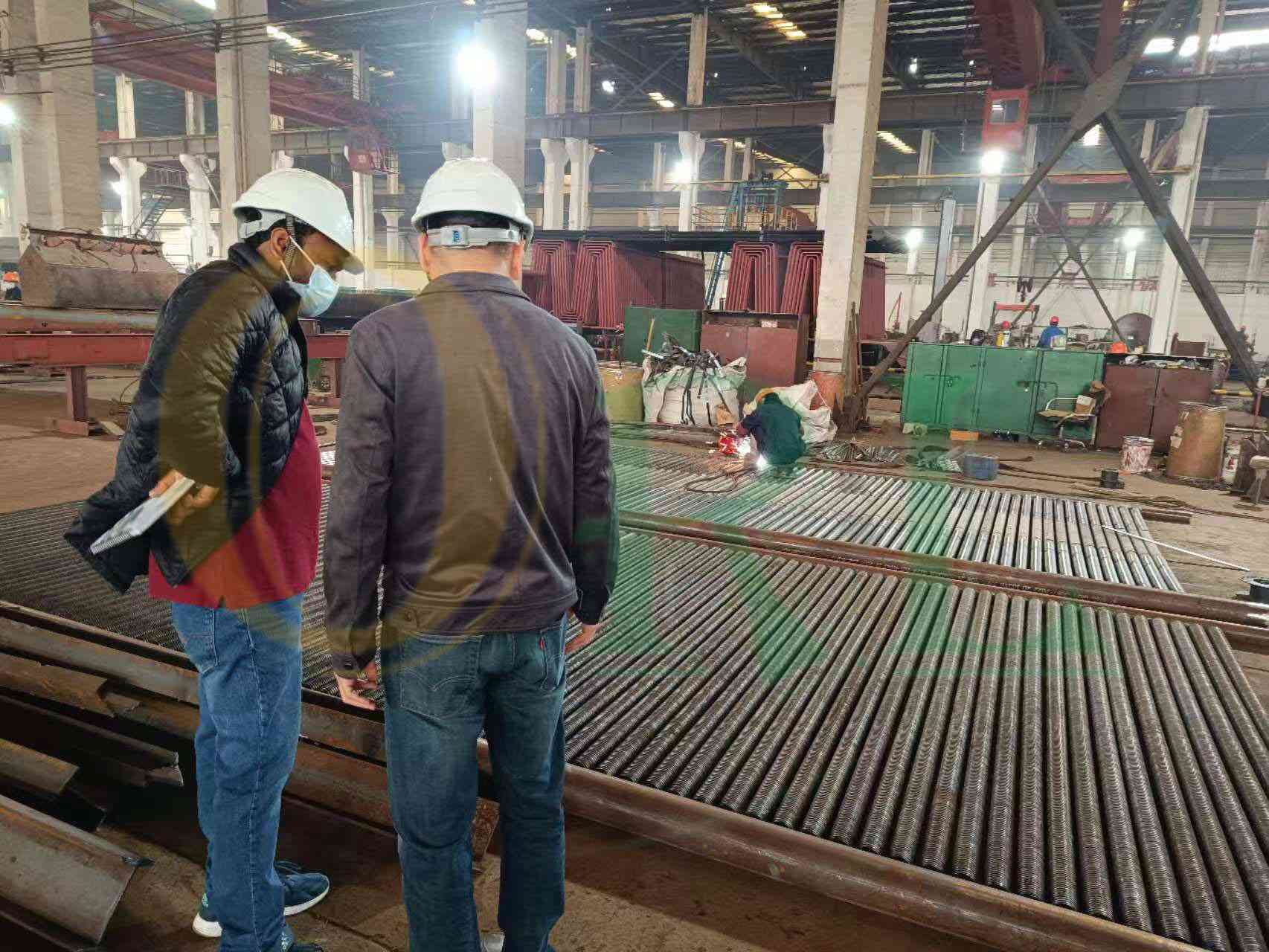
Customers inspect the PWHT furnace, review NDT reports, and witness hydrostatic testing during factory visits.
Frequently Asked Questions
Boiler Header FAQ
Common questions from EPC contractors, boiler OEMs, and plant engineering teams about header specification, PWHT, NDT, and lead time.
What information is needed to get a quotation?
The fastest route is to send your header drawing. If no drawing exists yet, we need the following to prepare a quotation:
- • Header position in boiler (economizer / superheater / water wall / other)
- • Design pressure (bar or psi)
- • Design temperature (°C or °F)
- • Shell OD and required wall thickness (or let us calculate from design conditions)
- • Shell material grade (or advise us of design temperature and we'll confirm grade)
- • Shell length
- • Number of tube stubs, stub OD, stub wall, and stub pitch along the header
- • Main connection nozzle size(s) and schedule
- • Drain, vent, and inspection nozzles
- • Applicable code (ASME Section I / GB/T 16507 / EN 12952 / IBR / other)
- • Quantity (single header, inlet+outlet pair, or full set for a tube bank)
- • Required delivery date and destination port
If you have a similar existing header to replace, a sketch with dimensions and a clear note of the applicable code is sufficient to start. We will generate the full drawing for approval before fabrication.
What is the difference between a header and a steam drum?
The physical distinction is primarily diameter and function:
- • A header is a relatively small-bore pressure vessel (typically 100–400 mm shell OD) whose function is purely hydraulic — collecting or distributing flow. It carries either single-phase water or single-phase steam. Headers do not separate phases.
- • A steam drum is a large-bore vessel (typically 800–2,000 mm shell OD) that performs steam-water separation — it contains a steam-water mixture and uses internal separators to produce dry saturated steam from the steam-water mixture rising from the furnace water walls.
In terms of fabrication: steam drums are governed by the pressure vessel sections of the code (ASME Section I PG-67 through PG-72) and require full volumetric examination of all seams. Headers are smaller and can use alternative examination methods for lower-pressure service, though large high-pressure headers are treated very similarly to steam drums in terms of NDT requirements.
When is PWHT required and what does ORL Power's process involve?
PWHT is triggered by material grade and wall thickness:
- • SA-106 carbon steel: required when any joint wall exceeds 32 mm — most economizer and water wall headers do not reach this, but we confirm each order.
- • SA-335 P11: required above 16 mm wall. Superheater headers in P11 usually trigger PWHT.
- • SA-335 P22: mandatory regardless of wall thickness.
- • SA-335 P91: mandatory, with strict temperature control — hold at 730–780°C, followed by hardness test to confirm the tempered martensite microstructure is within the acceptable hardness range.
Our in-house furnace accepts full header assemblies. Calibrated type-K thermocouples are attached to the header body. The controller records temperature versus time continuously from preheat through hold and controlled cool-down. The time-temperature chart is issued as part of the standard documentation for every PWHT job — not produced only on request.
Can you supply headers together with the tube coils or panels they connect to?
Yes — this is a common supply arrangement and in many cases the better option. When headers and tube coils come from different fabricators, the connections between them are the most common source of fitment problems on site. ORL Power fabricates both the headers and the tube coils in the same facility, and the connections between them are confirmed by trial assembly before despatch.
For complete packages, we issue a single code data report (ASME Form P-1 or equivalent) covering the whole assembly — header pair, tube coils, and associated fittings — which simplifies the client's documentation management and the third-party inspection scope. Products we supply as complete packages: economizer (headers + tube coils), superheater / reheater (headers + tube coils), water wall panel (headers + membrane panel).
What NDT is performed and what documentation is issued?
NDT scope for ASME Section I headers:
- • Girth welds and shell seams: radiographic examination (RT) to ASME Section I PW-51, or ultrasonic examination (UT) where RT is impractical. Acceptance per ASME Section I PW-51.2.
- • Nozzle attachment welds: magnetic particle (MT) or dye penetrant (PT) after PWHT. 100% of nozzle welds on Class 1 headers.
- • Hardness survey (P22, P91): Brinell hardness recorded after PWHT at each weld seam. P91 acceptance: 190–265 HBW.
- • Hydrostatic test: at 1.5× design pressure (ASME PG-99). Hold time minimum 30 minutes. No visible leakage or permanent deformation.
Documentation issued with every header: 3.1 MTCs for shell pipe and all nozzle forgings, weld map and weld log, WPS/PQR references, PWHT chart (where applicable), hardness test report (P22/P91), NDT report with film/images, hydrostatic test certificate, dimensional inspection report, and code data report with stamped nameplate.
What are typical lead times?
Lead times from drawing approval (or from our issued drawing if we generate the drawing from design conditions):
- • Carbon steel headers, SA-106 (no PWHT required): 6–10 weeks
- • Carbon steel headers, SA-106 (PWHT required, heavy wall): 8–12 weeks
- • SA-335 P11 headers: 10–14 weeks (alloy pipe procurement adds time)
- • SA-335 P22 headers: 12–16 weeks
- • SA-335 P91 headers: 14–20 weeks (P91 pipe lead time + mandatory PWHT and hardness testing)
Complete packages (headers + tube coils) follow the longer of the two component lead times. Lead times are confirmed at order placement with a milestone schedule — not estimated at delivery time.
Have a technical question not covered here?
Ask Our Engineering TeamGet Your Quote
Contact Our Engineering Team
Send your header drawing or design conditions — design pressure, design temperature, shell OD, material grade, nozzle list, applicable code. We reply within 24 hours with pricing and lead time.
Get Your Header Quote
Share your design conditions — we reply within 24 hours with pricing and lead time confirmation.
What to Include in Your Inquiry
- • Header position (economizer / superheater / water wall)
- • Design pressure (bar or psi)
- • Design temperature (°C)
- • Shell OD × wall thickness (mm)
- • Shell material grade (or we'll advise)
- • Tube stub: OD × wall, pitch, quantity
- • Main connection nozzle sizes
- • Applicable code (ASME / GB / EN / IBR)
- • Quantity and required delivery date