
Boiler Finned Tubes
Extended-surface tubes for economizers, waste heat boilers, and air preheaters. Fins increase the outer heat transfer area by 3–6× over bare tube— the proven way to raise efficiency in clean flue gas applications without enlarging the boiler footprint.
Fundamentals
What Are Finned Tubes?
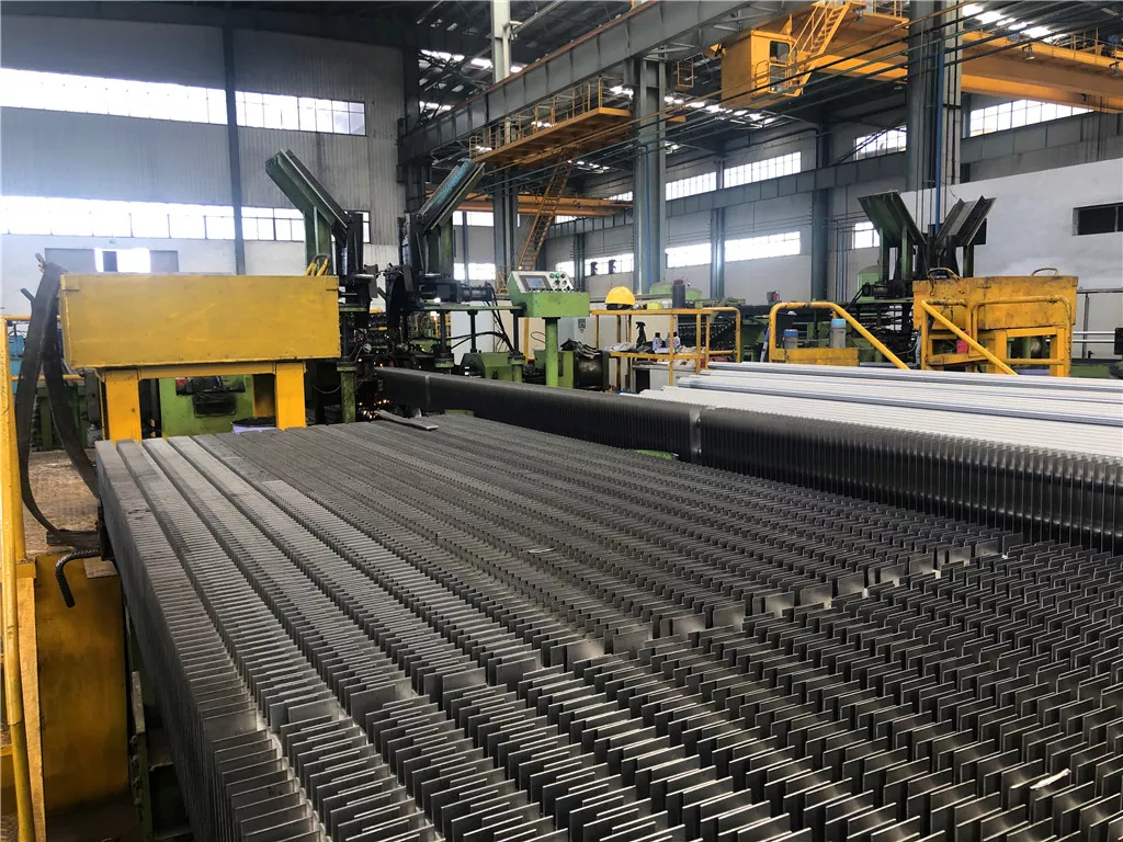
Finned tubes are plain boiler tubes with metal fins attached to the outer surface. The fins dramatically increase the area available for convective heat transfer between the hot flue gas outside and the working fluid inside — without increasing the number of tube passes or the duct volume.
Why Fins Work
Where They Are Used
- Economizer coil banks — feed water preheating
- Waste heat boilers — cement, glass, gas turbine
- Air preheater tube banks
- Heat recovery steam generators (HRSG)
- Package boiler convection sections
- Sugar mill bagasse boiler economizers
Product Range
Fin Types
The right fin geometry depends on flue gas dust loading, required heat transfer coefficient, and operating temperature. Three configurations cover the full range of industrial applications.
Spiral Fin
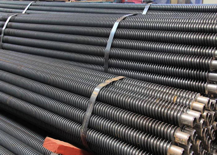
A continuous steel strip wound helically around the tube and attached by high-frequency resistance welding. Available in solid or serrated (segmented) profiles — solid for moderate dust loading, serrated where a 20–30% boost in heat transfer coefficient is needed on clean gas streams. The dominant fin type for economizers, superheaters, and waste heat boilers on gas and light-oil fuels.
- Solid profile: lower pressure drop, moderate dust tolerance
- Serrated profile: highest heat transfer on clean gas
- Wide tube grade and diameter compatibility
H-Type Fin
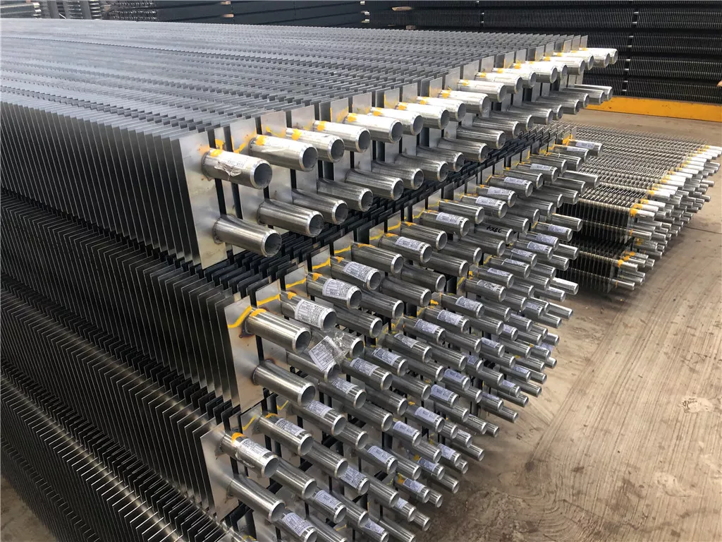
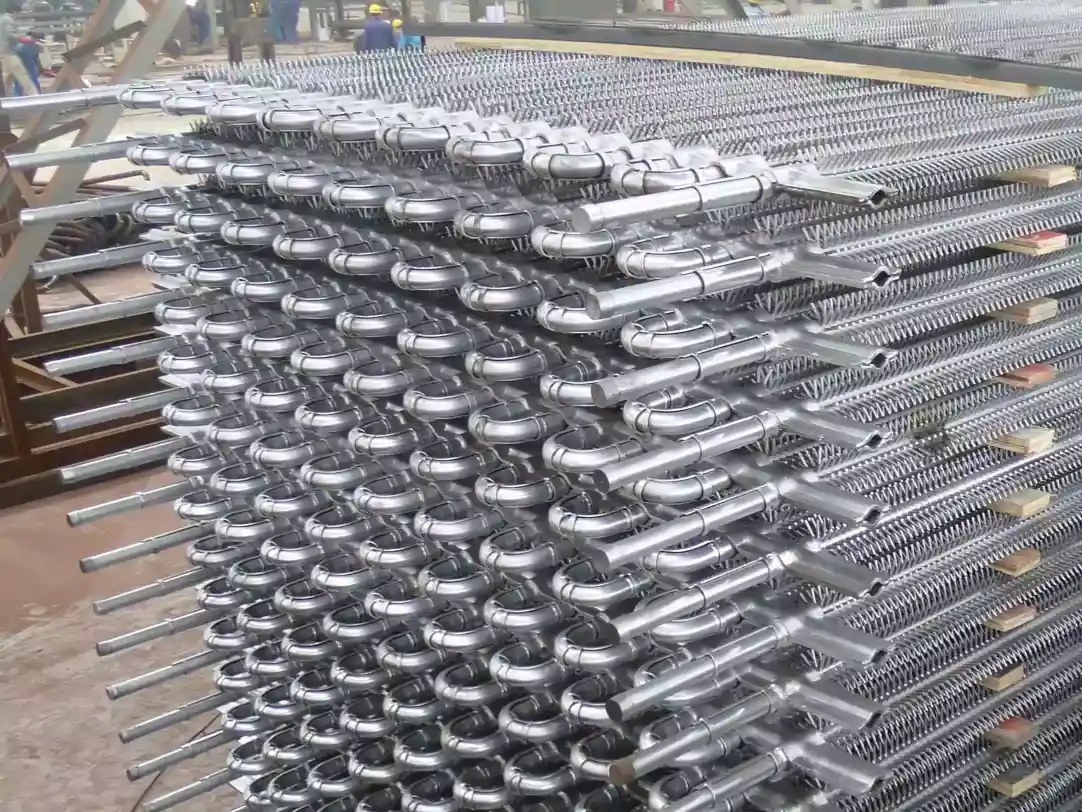
Two flat rectangular fin plates welded symmetrically to opposite sides of the tube, forming an H-profile when viewed end-on. The wide longitudinal pitch and smooth flat surfaces shed ash deposits far more effectively than helical fins — making H-type the preferred choice for coal-fired boiler economizers and other applications with significant fly-ash loading where spiral fins would foul and blind.
- Superior anti-fouling vs. spiral fin in dusty gas
- Lower pressure drop across the tube bank
- Standard choice for coal-fired boiler tail flue economizers
Studded
Individual cylindrical studs arc-welded directly to the tube OD in a helical or square pitch pattern. Where any fin geometry would plug with ash, corrode in aggressive flue gas, or exceed the fin attachment temperature limit, studs are the engineered solution — a compact extended surface that tolerates extreme dust loading, corrosive atmospheres, and the highest operating temperatures of all three types.
- CFB boiler convection sections
- High-sulphur or alkali-rich flue gas
- Waste-to-energy boiler upper furnace
Quick Selection Guide
| Application | Spiral Fin | H-Type | Studded |
|---|---|---|---|
| Natural gas / LPG boiler | ✓ Best | — | — |
| Coal-fired boiler economizer | — | ✓ Best | — |
| Biomass boiler (low ash) | ✓ Wide pitch | ✓ | — |
| Cement / glass kiln WHB | ✓ | ✓ Best | — |
| CFB / high-dust flue gas | — | — | ✓ Best |
| Waste-to-energy upper furnace | — | — | ✓ Best |
Not sure which type fits your gas conditions? Share your application — we'll advise in one reply.
Get Technical AdviceQuality Assurance
Materials & Standards
Tube grade is selected by operating temperature and pressure. Fin material is typically matched to tube grade — carbon steel fin on carbon or low-alloy tube is the standard; stainless or alloy fin is specified where the fin surface operates above the carbon steel oxidation limit.
Tube & Fin Material Combinations
Fin Attachment Method
Weld
Stud
Bond quality test: HF-welded fins are tested by peeling a fin strip section. The weld is accepted when the tube base metal tears before the fin-to-tube bond fails — confirming the weld is stronger than the parent material. Test records are kept in the quality file.
Certifications & Capability Evidence
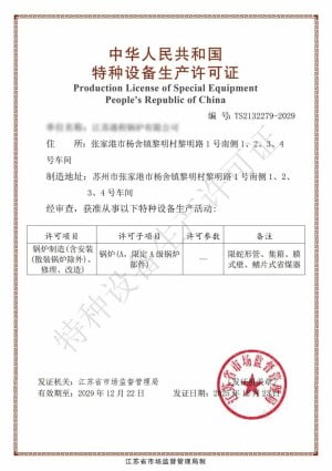
Grade A Boiler
ISO 9001
ISO 14001
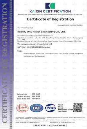
ISO 45001
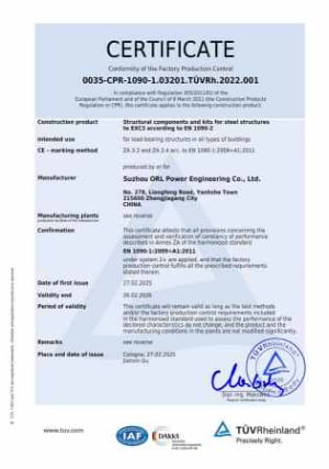
EN 1090
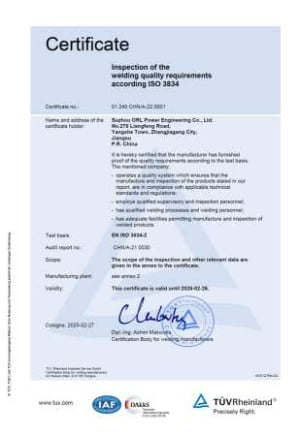
EN 3834
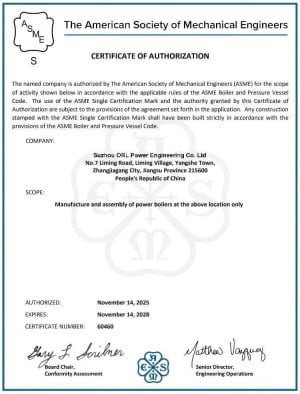
ASME S
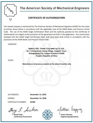
ASME U
Our Advantage
Why Choose ORL
A finned tube with a poor weld bond loses heat transfer efficiency within months of service — and the failure is invisible until the boiler underperforms. Fin attachment quality is not something to leave to chance or to the lowest-cost quotation.
Weld Bond Peel Test — Every Batch
HF weld quality is verified by destructive peel test on every production batch — not periodically, not on samples selected in advance. The test result and a photograph of the peeled section are included in the quality file for each order.
Fin Pitch Tolerance ± 1mm
Fin pitch directly affects both heat transfer performance and the minimum gap available for gas and ash to pass through. We hold pitch tolerance to ± 1mm across the tube length — verified by dimensional inspection on finished tubes before despatch.
Full Material Traceability
Tube and fin strip EN 10204 3.1 Mill Test Certificates are retained and cross-referenced to each production order. For alloy grades (T11, T22), PMI confirmation that the incoming material chemistry matches the certificate is standard — not an option.
Fin Geometry to Your Drawing
We manufacture to your specified fin height, thickness, pitch, and segment width — not to a fixed catalogue. If you have a qualified supplier's product to match, send the drawing or sample; we produce to the same geometry and confirm compliance before shipment.
Part of a Complete Pressure Parts Package
Finned tubes are manufactured in the same facility as economizer headers, steam drums, and superheater coils. If your project needs finned tubes plus assembled components, a single-source package eliminates the interface coordination between a tube supplier and a fabrication shop.
Reliable Delivery on Production Quantities
Finned tube orders are scheduled as production runs, not one-off fabrication jobs. Standard carbon steel orders ship in 4–6 weeks from drawing approval. Alloy grade orders are confirmed at quotation stage with a specific delivery date — not an estimate.
Tell us your tube OD, fin geometry, and gas temperature.
We'll confirm material grade, fin type, and delivery timeline in one reply.
Applications
Industries We Serve
These are boiler pressure parts — tubes that carry high-pressure feedwater or steam through the flue gas convection pass, governed by ASME Section I, GB/T 16507, or EN 12952. The buyer is typically a boiler OEM, an EPC contractor building a new plant, or a plant maintenance team replacing worn tubes during a scheduled outage.
Economizer Manufacturers
The primary market for finned tube supply. Economizer fabricators buy finned tubes in production quantities and assemble them with headers and casing. ORL Power supplies the tubes; the fabricator handles assembly and installation.
Waste Heat Boiler Builders
Cement kiln, glass furnace, and steel mill WHBs use finned tubes extensively in their low-temperature convection sections where gas is clean and compact design reduces civil costs. Gas turbine HRSG builders also specify serrated fin tubes for maximum surface density.
Biomass & WtE Plants
Biomass plants with effective dust collection upstream can use solid finned tubes at wide pitch in the cooler convection zones. Waste-to-energy upper furnace sections use studded tubes where the gas contains chlorine and alkali that would corrode helical fins.
Sugar Mill & Power Plant Maintenance
Plant maintenance teams replacing worn or eroded finned tubes during scheduled outages. Sugar mills running bagasse-fired cogeneration boilers and coal or gas power stations both require replacement finned tube supply matched to the existing bundle geometry — including exact fin height, pitch, and tube OD.
Tell us your application and gas conditions.
We'll confirm fin type, tube grade, and production lead time in one reply.
Manufacturing Process
Factory & Process
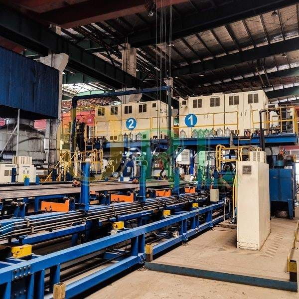
Finned tube quality is determined during the winding process — not at the end. Each production step is controlled and documented so that by the time tubes leave the factory, the quality record is already complete.
Key Production Steps
Customer Visits & Factory Evidence
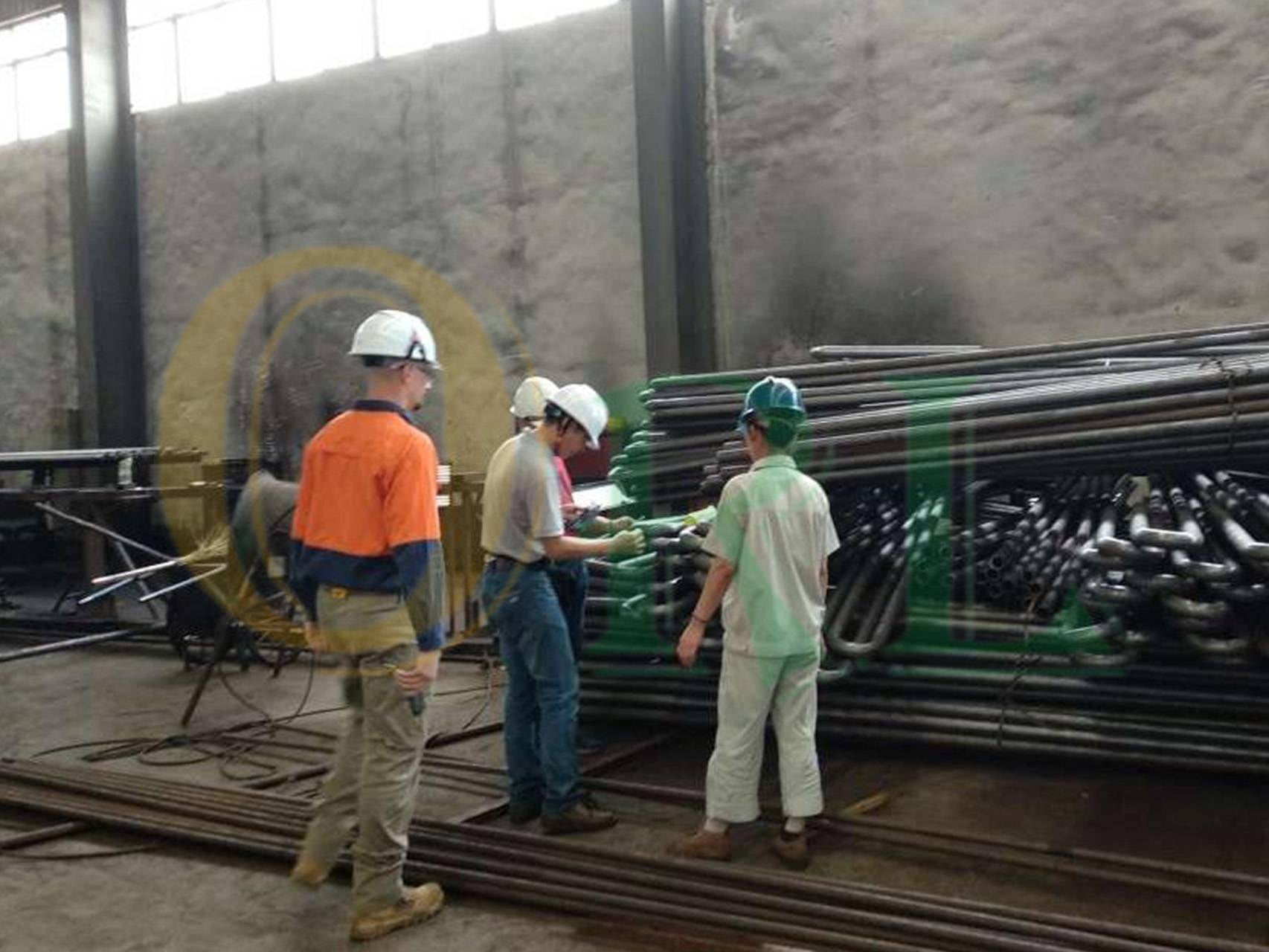
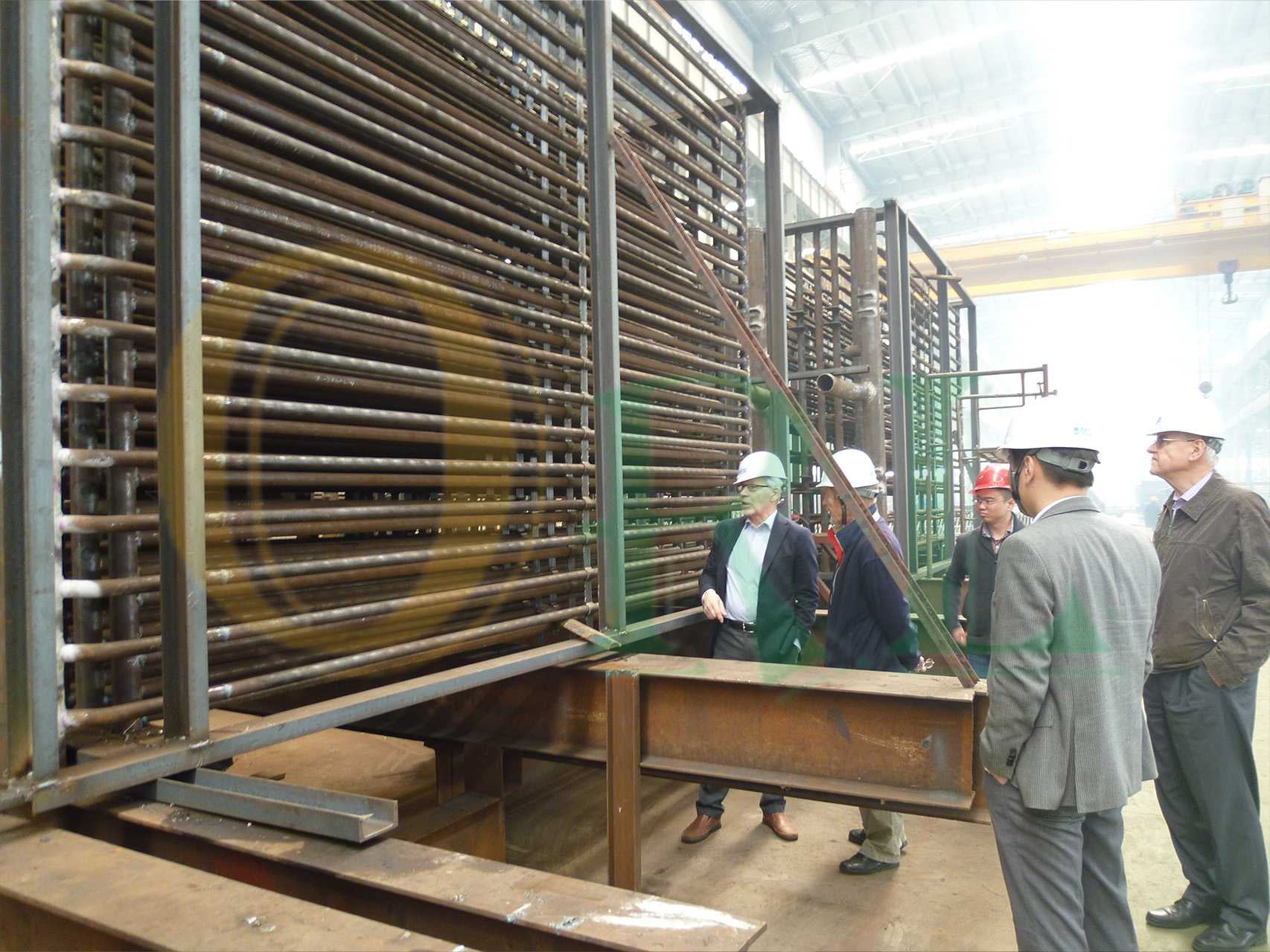
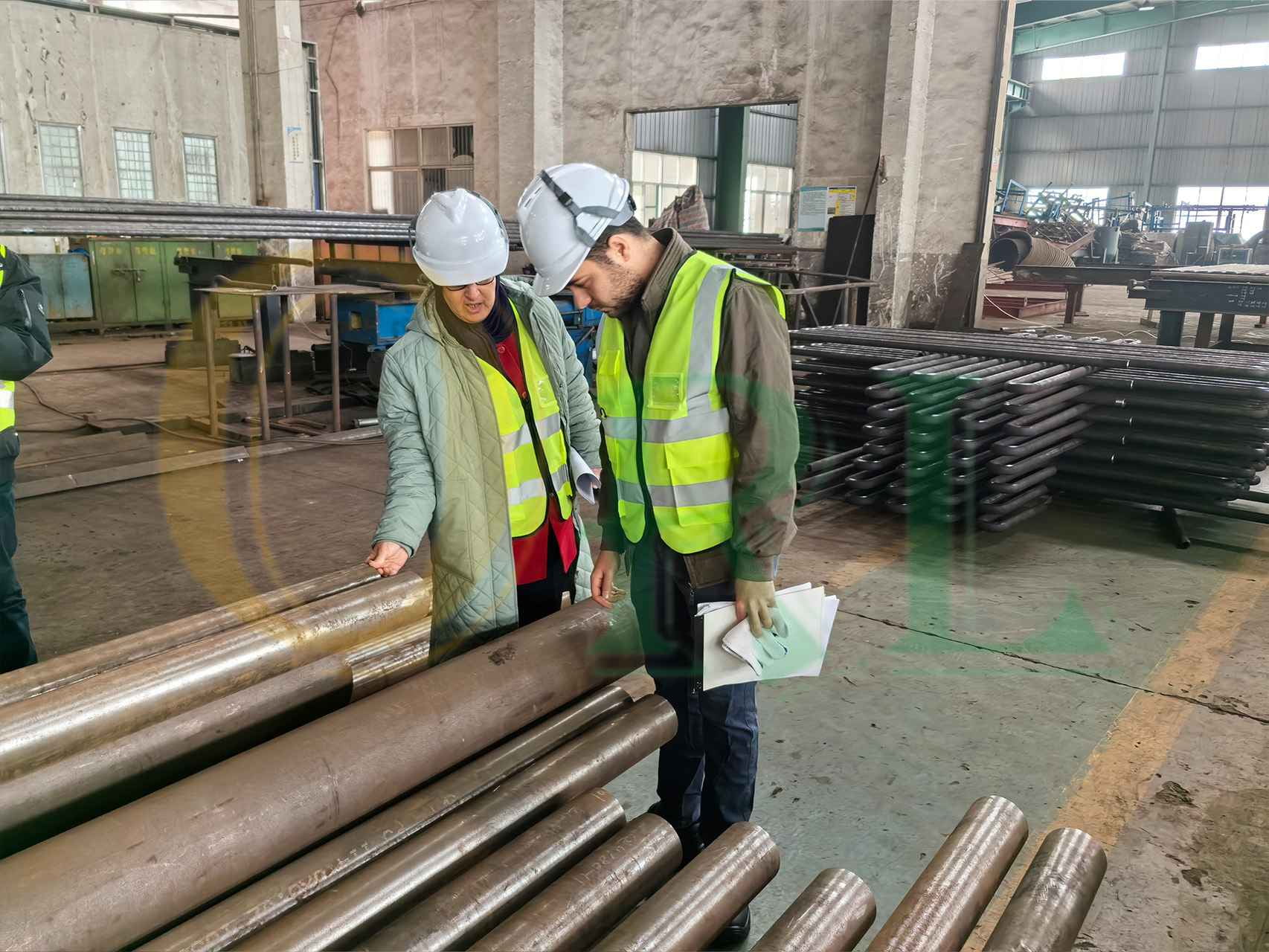
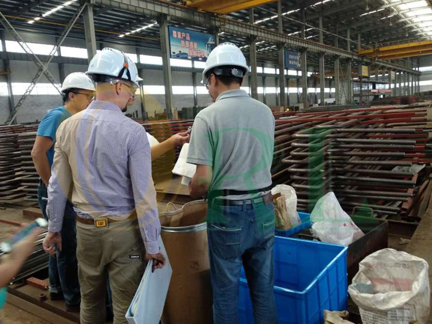
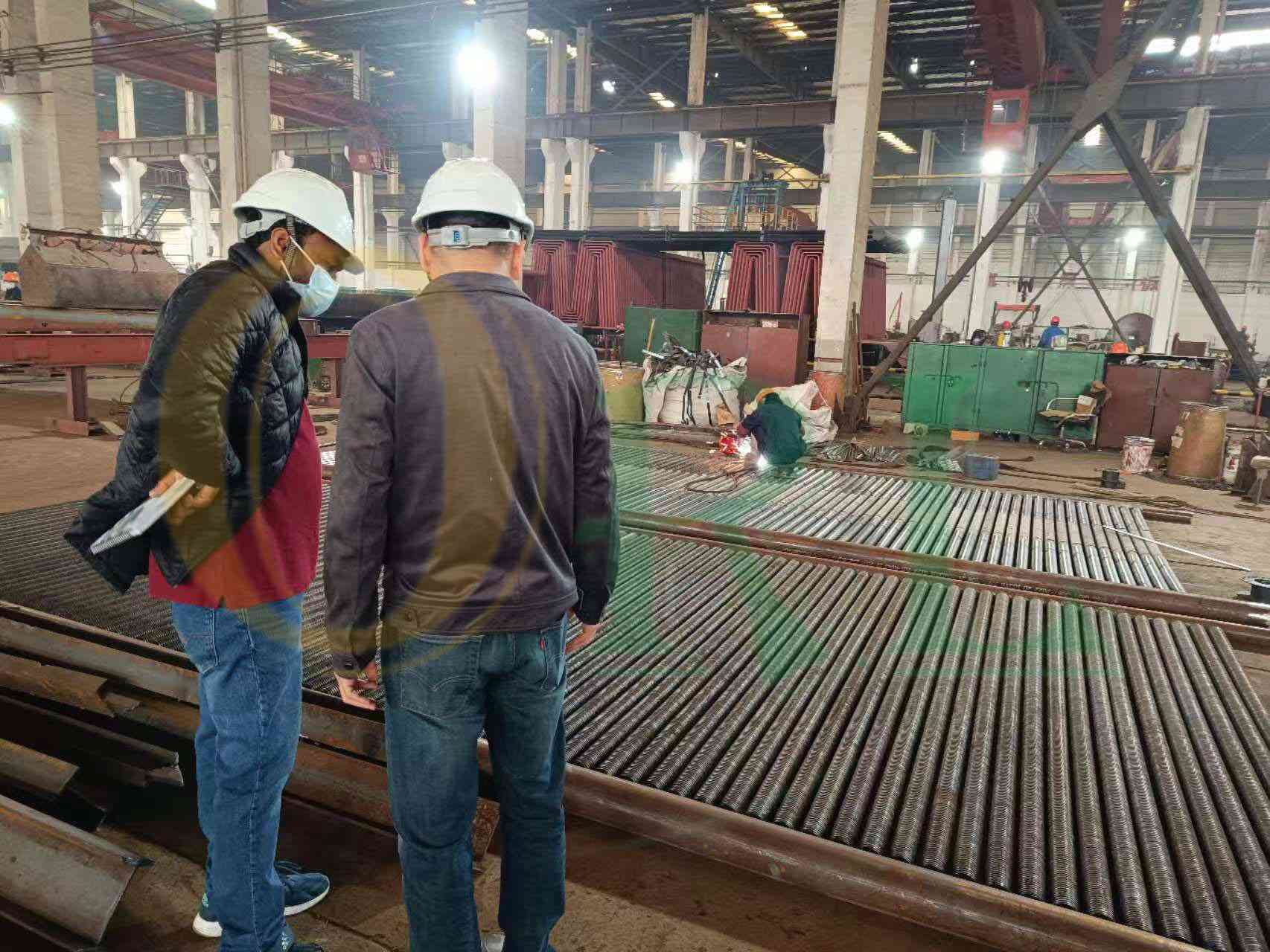
Customers inspect the HF winding line, peel test samples, and dimensional records during factory visits.
Frequently Asked Questions
Finned Tube FAQ
Common questions from economizer fabricators, boiler OEMs, and procurement engineers about finned tube specification, quality, and supply.
What information is needed to get a quotation?
Finned tube quotation is straightforward once the geometry is confirmed. We need:
- • Tube OD and wall thickness (e.g. 38 × 3.5 mm)
- • Tube material grade (SA-210 A1 / SA-210 C / T11 / T22 / other)
- • Fin type: solid, serrated, or studded
- • Fin height and thickness (e.g. 19 mm × 1.2 mm)
- • Fin pitch (e.g. 6 mm)
- • Fin material (carbon steel / stainless / alloy)
- • Segment width -- for serrated fin only (e.g. 4 mm)
- • Tube length (delivery length, not bundle length)
- • Quantity (metres or number of tubes)
- • Applicable code or standard (ASME / GB / EN / none)
- • Required delivery date and destination port
If you have a drawing, sending it is the fastest route. If you are still at design stage, share the application and gas conditions -- we can advise on a suitable geometry.
How do I choose between solid fin and serrated fin?
The deciding factor is gas dust loading and the sensitivity of your design to pressure drop:
- • Serrated fin raises the heat transfer coefficient by 20-30% over a solid fin at the same pitch and height -- but the serration segments create more turbulence and therefore higher gas-side pressure drop. This is the right choice when gas is clean (natural gas, LPG, clean gas turbine exhaust, cement kiln after effective cyclone) and you want to minimise tube count or bundle depth.
- • Solid fin has lower pressure drop and tolerates a moderate level of gas dust without the segment notches trapping ash. At wider pitch (8-12 mm), solid fin tubes work in applications with light particulate loading -- biomass boilers with good dust collection, or lower-temperature convection zones of coal boilers.
If your gas is borderline, the minimum fin channel width (fin pitch minus fin thickness) is the practical criterion: a 5 mm clear channel is the general lower limit for self-cleaning in light-dust gas. Below this, solid fin at wider pitch or bare tube is safer.
How is HF weld bond quality verified?
HF weld bond is verified by destructive peel test on every production batch:
- • A section of fin strip is mechanically peeled back from the tube using a lever or peel tool.
- • Acceptance criterion: the tube base metal must tear before the fin-to-tube weld bond fails. If the fin separates cleanly at the weld line, the batch is rejected and parameters are reviewed.
- • The peel test result -- pass/fail, photo of the fractured surface, and batch reference -- is documented in the quality file and supplied with the delivery documentation.
This test cannot be replaced by visual inspection of the weld bead alone. A bead that looks correct can still have an unbonded zone if power or tension drifted during winding. The peel test is the only definitive proof of bond integrity.
Can you match the geometry of our current supplier's tubes?
Yes, within the range our equipment covers. Send the drawing from your current supplier, or a sample tube -- we will measure fin height, thickness, pitch, and segment width and manufacture to the same specification. A pre-shipment dimensional report confirms compliance before the order ships.
The only cases where we cannot match exactly are fin geometries outside our machine range (very high or very narrow fins) or unusual fin materials we do not stock. Both would be flagged at quotation stage with the nearest alternative we can offer.
What documentation comes with the tubes?
Standard documentation included with every delivery:
- • Tube EN 10204 3.1 Mill Test Certificate (chemistry + mechanical properties)
- • Fin strip material certificate
- • PMI record -- for alloy grade tubes (T11, T22)
- • HF weld peel test record with fractured surface photograph
- • Dimensional inspection report (fin height, pitch, OD over fins, tube length)
- • Packing list with tube count and total metres
Third-party inspection (SGS, BV, TÜV, Intertek) can be arranged on request. A test certificate for a specific standard (e.g. EN 10204 3.2 -- inspector-witnessed) is available at additional cost.
What is the typical lead time and minimum order quantity?
Lead times from drawing or specification approval:
- • Carbon steel (SA-210 A1 / SA-210 C) solid or serrated fin: 4-6 weeks
- • T11 tube, carbon steel fin: 6-8 weeks (alloy tube procurement adds time)
- • T22 or higher alloy, PWHT required: 8-12 weeks
- • Studded tube (carbon steel studs): 5-7 weeks
- • Studded tube (stainless studs, TP304H/TP316): 6-9 weeks
There is no fixed minimum order quantity -- we supply both small replacement quantities and large production runs. Very small quantities (under ~200 m) carry a setup charge that is quoted transparently; it does not affect lead time.
Have a technical question not covered here?
Ask Our Engineering TeamTechnical Guide
Boiler Finned Tubes Manufacturer for Economizers and Heat Recovery Equipment
Boiler finned tubes increase external heat transfer area and are widely used in economizers, air preheaters, waste heat recovery units and heat exchange equipment. ORL manufactures H-fin tubes, spiral fin tubes and custom finned tube assemblies according to drawings, materials, tube size, fin pitch and inspection requirements.
What Are Boiler Finned Tubes?
Boiler finned tubes are tubes with welded or attached fins that increase heat transfer surface area. They help recover more heat from flue gas or process gas where compact heat transfer surfaces are required.
H Fin Tubes and Spiral Fin Tubes
H-fin tubes are often selected for boiler economizers and flue gas heat recovery, while spiral fin tubes are used in different heat exchange layouts. Selection depends on gas condition, fouling risk, pressure drop and cleaning requirements.
Finned Tube Manufacturing Process
- Confirm base tube, fin material and drawings
- Prepare tube and fin strip or fin plate
- Weld or attach fins according to design
- Control fin height, pitch and alignment
- Perform dimensional and weld inspection
- Pack for export or assembly into modules
Where Are Finned Tubes Used?
- Boiler economizers
- Air preheaters
- Waste heat recovery units
- Industrial heat exchangers
- Replacement heat transfer tube bundles
Custom Finned Tubes According to Drawings
ORL reviews tube drawings, fin type, fin pitch, tube material, operating conditions and inspection requirements before fabrication. This helps avoid mismatched fin geometry, unsuitable material or installation interface problems.
Finned Tubes FAQ
What are boiler finned tubes?
They are tubes with fins used to increase heat transfer area in boiler and heat recovery equipment.
What is an H fin tube?
An H fin tube uses H-shaped fins welded to the tube, commonly used in boiler economizer applications.
What is a spiral fin tube?
A spiral fin tube uses a continuous fin wound around the base tube to increase surface area.
Can ORL manufacture finned tubes according to drawings?
Yes. ORL fabricates finned tubes according to drawings, tube material, fin geometry and inspection requirements.
What information is needed for quotation?
Please provide tube size, material, fin type, fin height, fin pitch, length, quantity, drawings and inspection requirements.
Where are boiler finned tubes used?
They are used in economizers, air preheaters, waste heat recovery units and heat exchange equipment.
Related Heat Recovery Products
Boiler Economizer · Boiler Air Preheater · Shell and Tube Heat Exchanger · Waste Heat Boiler
Need Custom Finned Tubes?
Send your tube drawings, fin type, fin pitch, material and quantity for ORL review.
Request Finned Tube QuoteGet Your Quote
Contact Our Engineering Team
Tell us your tube OD, fin geometry, material grade, quantity, and delivery requirement — we reply within 24 hours with pricing and lead time.
Get Your Finned Tube Quote
Describe your specification — we reply within 24 hours with pricing and lead time.
What to Include in Your Inquiry
- • Tube OD × wall thickness (mm)
- • Tube material grade
- • Fin type: solid / serrated / studded
- • Fin height × thickness (mm)
- • Fin pitch (mm); segment width if serrated
- • Fin material (CS / stainless / alloy)
- • Delivery length per tube (mm)
- • Quantity (metres or pieces)
- • Required delivery date